The takeoff calculation is arguably the most complex type of
computation, involving numerous considerations.
We meticulously examine each step to deliver the most precise
result available for your flight simulation experience.
The take-off phase spans from brake release to either the point
where the airplane reaches 1500 feet or the height necessary to
clear the last take-off obstacle if it's higher.
-
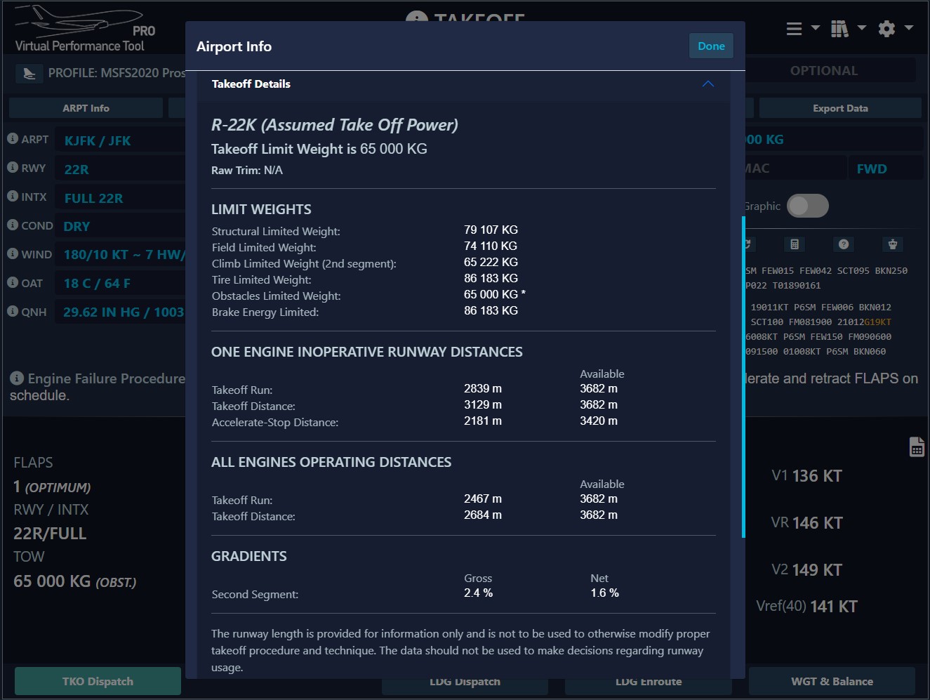
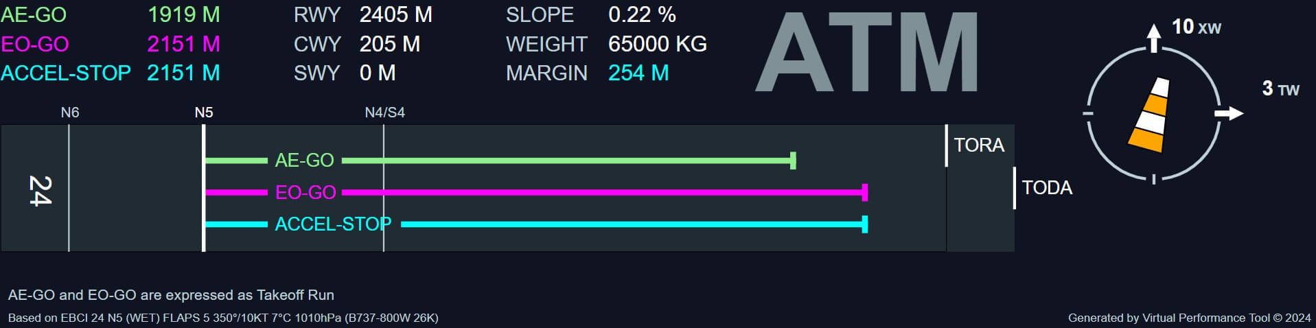
Field Length:
Ensures adequate runway for safe continuation or rejection of
takeoff in the event of an engine failure, and sufficient runway
for a normal, all-engines takeoff.
Take-off distance is determined between the start of the
take-off roll and the point when the airplane reaches 35 ft (15
ft on wet).
The engine failure is considered to take place at VEF
and to be recognized (action taken) at V1.
If decision at V1 is to continue, a take-off distance
is defined by the airplane having reached a height of 35 ft (15
ft on wet).
If decision at V1 is to stop, an accelerate-stop
distance (ASD) is then defined.
The safety margin consists in adding 15 % to the distance
demonstrated by flight test.
-
Minimum Climb Requirement (One Engine Inoperative):
Ensures the aircraft has sufficient climb capability throughout
takeoff.
Includes the required limitations to the take-off weight in
order to achieve minimum climb performance. It is worth noting
that, at this stage, those minimum performances have nothing to
do with the obstacle clearance criteria. The obstacle clearance
will be treated separately and may, of course, lead to higher
performance penalties.
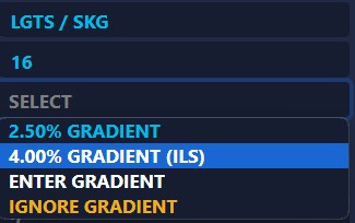
The minimum climb gradient criteria correspond to still air
conditions, while the obstacle clearance takes the wind into
account.
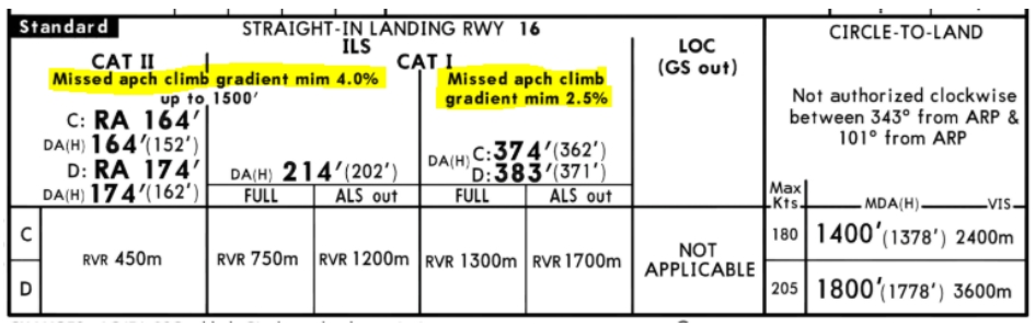
The takeoff is divided into four sections, each with a minimum
climb gradient required for certification, up to an altitude of
1500 feet. This gradient is solely dependent on the number of
engines the aircraft is equipped with.
-
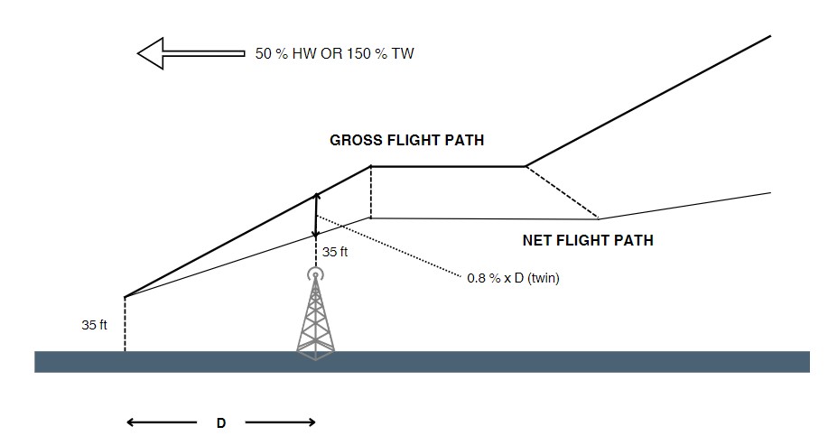
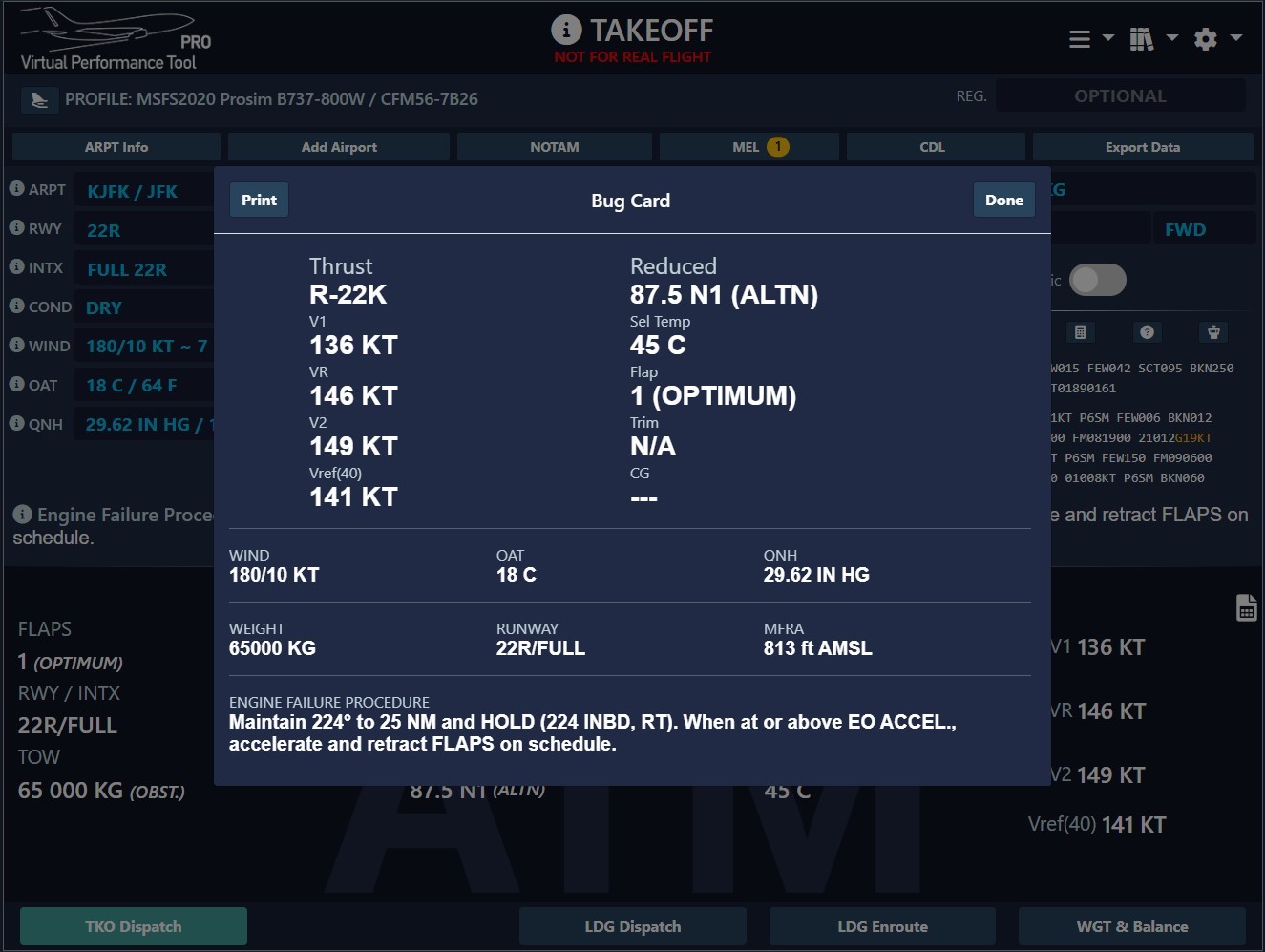
Obstacle Clearance Requirement:
Ensures the aircraft can clear all obstacles with the required
margin, and this is precisely where the
Engine Failure Procedure can have a significant
impact.
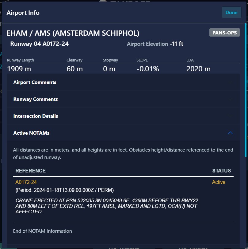
For obstacle clearance, a NET flight path must be taken into
account. This trajectory is virtual, achieved by reducing the
gross trajectories with a safety margin determined based on the
number of engines the aircraft possesses.
Furthermore, the winds used in the obstacle clearance computation
represent 50 % of the actual HW and 150 % of the actual TW
(airport wind).
Finally, the so computed net flight path must overfly the
obstacles by at least 35 ft.
-
Maximum Certified Tire Speed:
Limits the maximum ground speed before liftoff.
Tires are designed for a maximum ground speed. Its limiting effect
will be applicable for all T/O speeds up to VLOF.
Tire speed requirements have been checked and are not limiting for
normal conditions. However, these limits could be exceeded at
certain conditions where improved climb is used in conjunction
with downhill slope, tailwind, and/or high altitudes and
temperatures.
-
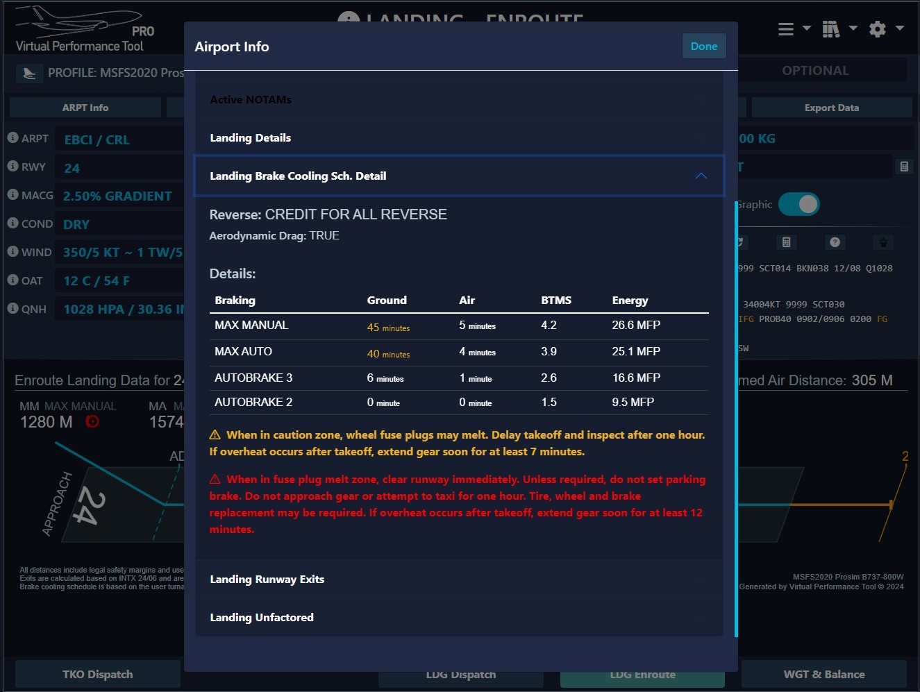
Brake Energy Requirement:
Sets the maximum amount of energy the brakes can absorb in the
event of a rejected takeoff.
Maximum brake energy absorption is limited by design and
certification.
VMBE (Maximum Brake Energy Speed) is the speed giving
a kinetic energy which is equal to the maximum brake energy.
V1 must never exceed VMBE. Should V1
exceed VMBE, weight must be reduced, or the analysis
must be done again with another flap setting or a lower
V1/VR.
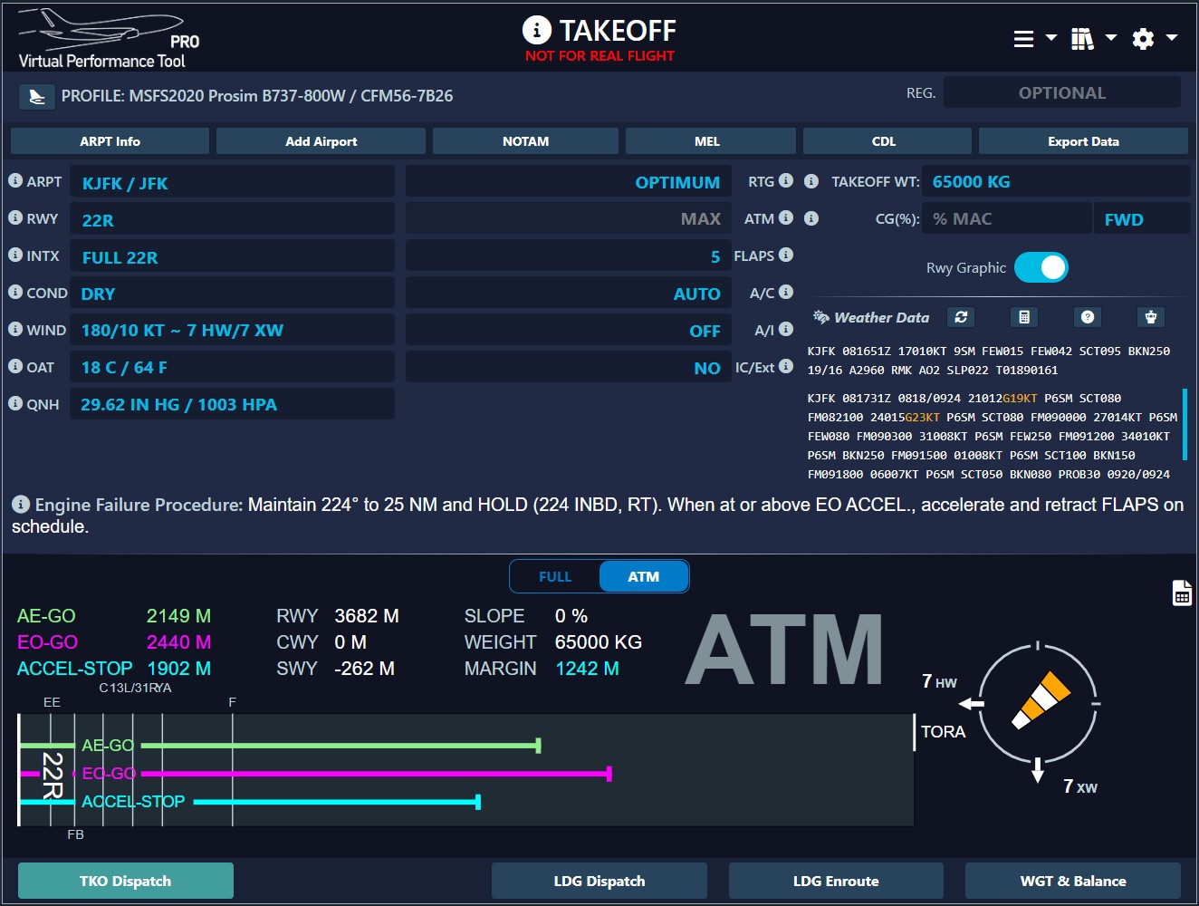
Optimum V1
V1 is the latest speed at which you can safely abort a takeoff, and
it's also the earliest speed at which you can proceed with the
departure.
However, fewer virtual pilots are aware that V1 actually
represents a range of speeds, typically set between:
The operator has the flexibility to configure their performance tool
according to their procedures. This includes selecting the preferred
value of V1 to be used.
-
Minimum V1: the minimum permissible V1 speed for the referenced
conditions from which the takeoff can be safely completed after
the critical engine has failed at the designated speed
(VEF). This option prioritizes shorter ASDR
(Accelerate-Stop Distance Required) but results in a longer
Engine-Out Go distance. Due to the smaller V1, it is
typically more inclined towards a "stop" decision during takeoff.
-
Maximum V1: the maximum possible V1 for the referenced
conditions at which a rejected takeoff can be initiated and the
aircraft stopped within the remaining runway (or runway plus
stopway where available). This option prioritizes a shorter
Engine-Out Go distance but results in a longer ASDR
(Accelerate-Stop Distance Required). Due to the larger
V1, it is typically more inclined towards a "go"
decision during takeoff. This is usually the closest one to
the CDU speeds.
-
Optimum V1: a flexible and optimized V1 that balances the
requirements of Takeoff Distance Required (TODR) and
Accelerate-Stop Distance Required (ASDR). It considers factors
such as wind, slope, and obstacle clearances to deliver the most
effective performance available.
-
V1 to achieve the highest possible performance
limited weight
-
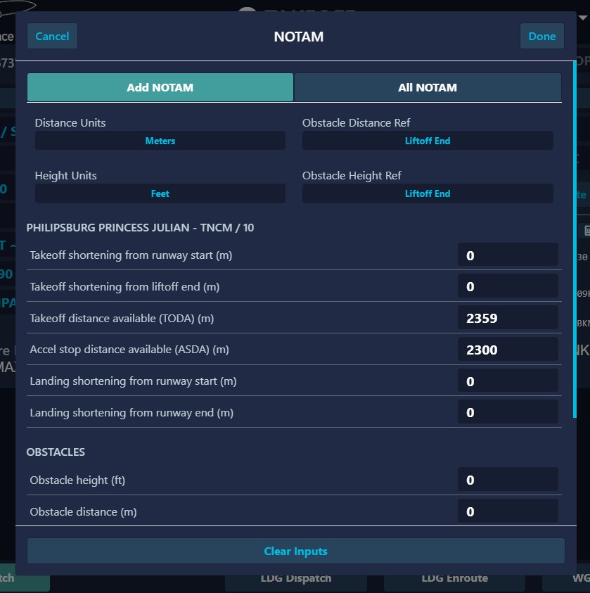
Unbalance for clearway and stopway of unequal usable lengths
- Unbalance for lineup distances of unequal lengths
-
Unbalance to meet V1MCG and VR
requirements
-
Unbalance to meet brake energy (VMBE) and obstacle
clearance requirements
- May not be compatible with FMC or QRH takeoff speeds
-
If a range of V1 is available, the balanced V1
will be shown in the output if it is within the range. If the
balanced V1 is not within the range, then either
the minimum V1 or the maximum V1 will be
shown, whichever is closer to the balanced V1.
Our tool is set to provide you with the
Optimum V1 for your
conditions, which may differ from the generic values given by your
CDU/MCDU. Understanding the theory will help you to maximize your
performances.
A reliable performance tool offers insights beyond the capabilities
of your aircraft's CDU/MCDU. Therefore, it's crucial to question any
discrepancies and
prioritize the outcomes provided by your performance tool.
We currently do not provide customization options for the V1
calculation method. However, this feature may be developed at a
later stage.
Improved Climb
The "Improved Climb" technique uses the excess runway available to
accelerate to higher takeoff speeds thereby achieving higher
gradient capability.
The excess gradient is achieved by using a heigher V2. To increase
V2:
- VR (rotation speed) must be increased
-
V1 must be increased to ensure sufficient speed is available to
continue the takeoff in case of engine failure
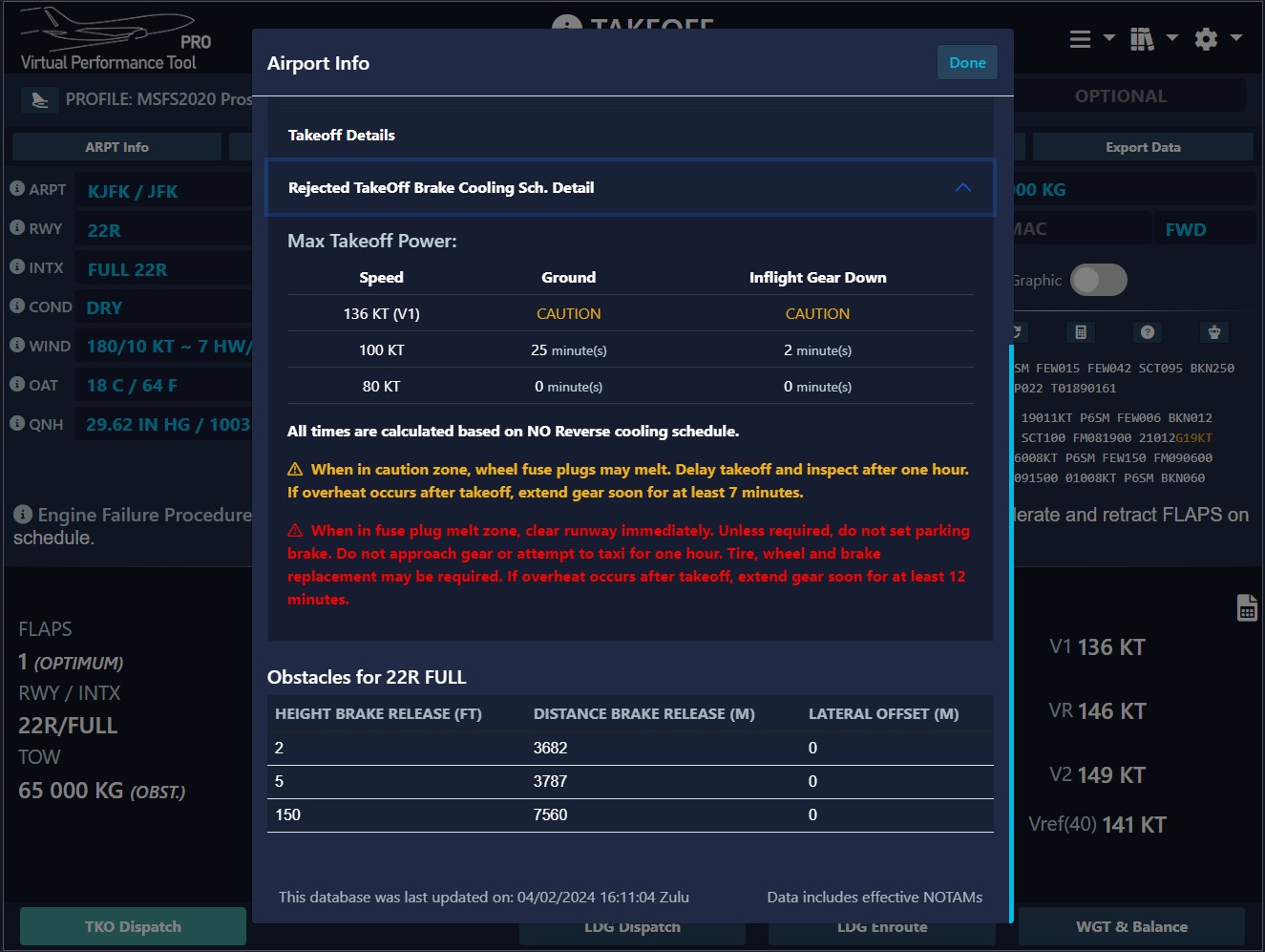
The excess speed must be cautiously managed, especially on very long
runways and at high weights, as your Performance-Limited Takeoff
Weight (PLTOW) could be restricted by tire limits. A rejected
takeoff at such speed and weight may lead to fuse plug melting.
This limitation can be realistically assessed using our
performance tool.
As per definition, the Improved Climb technique uses extra speed to
gain in climb performances. When this technique is available, the
Vspeed displayed by the CDU/MCDU
will NOT match the VPT calculations because there
is no "Improved Climb option". This is normal and realistic. You are
expected to utilize the results from your performance tool to
implement this technique.
Extended Second Segment
Typically, a standard Acceleration Height is determined in
accordance with operator procedures, with a legal minimum starting
point as low as 400 ft AGL. However, opting for too low an
acceleration height may pose conflicts with certain obstacles,
limiting your maximum takeoff weight. Conversely, selecting an
excessively high acceleration height may clash with engine
limitations.
The Maximum Takeoff Thrust (TOGA) is certified for use within a
maximum window of 5 minutes, extendable to 10 minutes with
manufacturer authorization. While this enhanced feature requires
additional maintenance considerations, it can significantly boost
performance, especially in scenarios with high obstacles surounding
the airport of departure.
Our premium package provides diverse profiles with various engine
certifications, allowing you to tailor your choice to specific needs
and optimize performance. This process is automatically reflected in
your Engine Out Acceleration Height / Minimum Flaps Retraction
Altitude.
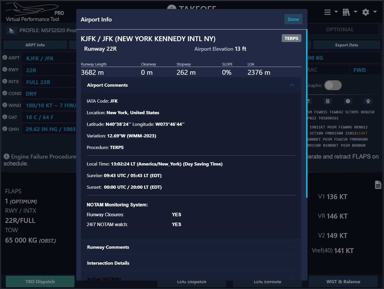
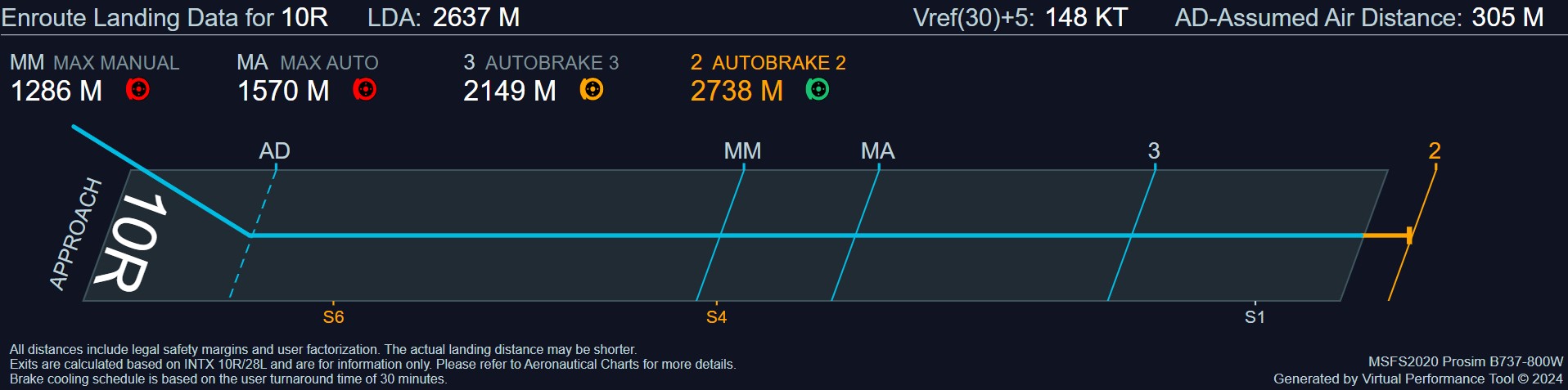
Loss of Runway Length due to Alignment
Airplanes typically enter the takeoff runway from an intersecting
taxiway. The airplane must be turned so that it is pointed down the
runway in the direction for takeoff. FAA regulations do not
explicitly require airplane operators to take into account the
runway distance used to align the airplane on the runway for
takeoff. On the contrary, EASA regulations require such a distance
to be considered.
At Virtual Performance Tool, we
conduct lineup corrections as part of our takeoff performance
calculations whenever the runway configuration prevents positioning
the airplane at the threshold. This adjustment is typically
necessary for a 90° taxiway entry or a 180° turnaround on the
runway. Detailed adjustments, as outlined in published tables, guide
this correction process.
Slippery vs Friction
Here's a fun fact you can explore with our
precise tool: A shallow layer of dry
snow can actually create a slippery runway surface, leading to an
increase in the Accelerate-Stop Distance Required (ASDR). However,
once the snow depth reaches a certain threshold, the accumulated
contaminant will induce friction, thereby reducing the ASDR.
Consequently, it's common to observe a lower Performance-Limited
Takeoff Weight (PLTOW) on runways with shallow snow depths compared
to those with deeper accumulations.